Sikorsky Product History
Sikorsky S-47 / VS-316A
Background
The Sikorsky S-47/VS-316A/R-4 model was the first production helicopter in the world and based on the successful VS-300A helicopter. It was designed with Sikorsky funds without Government assistance. On May 26, 1940 Igor Sikorsky visited the U.S. Army Air Corps, Material Division at Wright Field in Dayton, Ohio. Motion pictures of the VS-300 were shown that demonstrated the controllability of the Sikorsky design. The Air Corps was impressed but explained that there were insufficient funds available to fund a Sikorsky helicopter (They had invested in the Platt LePage XR-1 which had controllability problems.). However if they received a proposal from Sikorsky that was within the limited funding available it would be considered. On August 14, 1940 Sikorsky submitted a proposal to build one VS-316 helicopter for $50,000. A contract was signed on January 10, 1941. The original XR-4 design included 3 tail rotors: 2 horizontally mounted and one vertically.
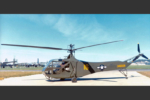
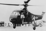
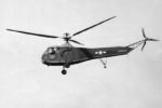
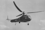
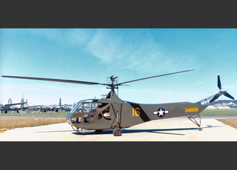 Sikorsky S-47/R-4B Army Serial No. 43-46506
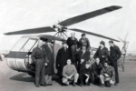
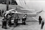
 The XR-4 Team Photo
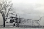
 XR-4 First Flight January 14, 1942
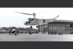
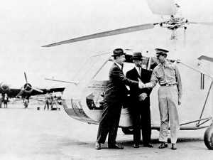
 First delivery of the XR-4 arrives at Wright Field, Dayton, Ohio, piloted by Lt. Col. Frank Gregory
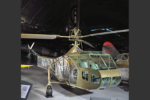
 Smithsonian XR-4C U.S. Army Serial No.41-18874
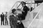
 Igor Sikorsky and Colonel Frank Gregory
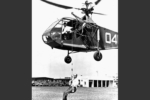
 Igor Sikorsky and USCG CDR Frank Erickson preparing to perform the first rescue hoist demonstration at U.S. Coast Guard Station Floyd Bennett Field, August 14, 1944
 USCG CDR Frank Erickson and Igor Sikorsky perform the first rescue hoist demonstration at U.S. Coast Guard Air Station Floyd Bennett Field, Brooklyn, NY, August 14, 1944
 XR-4 on the S.S. James Parker during shipboard demonstrations in July 1943

As the VS-300 helicopter developed, the design evolved to the single anti-torque tail rotor design. This design change to the XR-4 added $10,000 to the $50,000 contract. The estimated cost for the XR-4 development was $200,000. The XR-4 helicopters featured a 36 foot 3 bladed fully articulated main rotor and a 3 bladed tail rotor powered by a Warner Scarab 175 hp R-500-1 seven cylinder air cooled radial engine. The XR-4 had a 2 place side-by-side cockpit with dual flight controls. As a weight saving measure, only one main rotor pitch control lever (collective) was installed in the center of the cockpit One Experimental XR-4 helicopters was built The first flight was on January 14, 1942.
On April 20, 1942, a flight demonstration was scheduled to demonstrate that the XR-4 was ready for delivery. A requirement for this event was to demonstrate a power off autorotation. This had never been done in a Sikorsky helicopter and no procedures existed on how to accomplish an autorotation. Test pilot Les Morris was apprehensive when the engineers advised that they weren’t sure the XR-4 would be controllable during power off flight. Les Morris developed a procedure to autorotate the XR-4 and proved that the helicopter was both safe and controllable in autorotation.
The following film from 1943 is of Sikorsky Chief Test Pilot Les Morris in the R-4 demonstrating helicopter controllability and an autorotative landing within a foot of a handkerchief target.
The April 20, 1943 flight demonstration audience included Lt. Col. H. Frank Gregory, Major Leslie Cooper, and Mr. Mandel Lenkowsky from USAAF Material Division, Wright Field, Dayton Ohio, and representatives from other interested parties including: Allen W. Morris, Civil Aviation Authority (CAA); F.J. Baily, National Advisory Committee for Aeronautics (NACA); Commander W. J. Kossler, U.S. Coast Guard; Wing Commander R.A.C Brie; British Air Commission; Commander J. H. Millar, Royal Navy; Colonel George L. King and Colonel P.E Gabel, U. S. Army Armored Forces. The visitors were very impressed by the demonstration which included:
- Vertical ascents and descents, hovering, sideways and backward flying.
- The accurateness of control was demonstrated by “spearing” a 10 inch ring with the pitot tube and lifting it off a pole and delivering it to Igor. Sikorsky’s hand while hovering a few feet off the ground.
- Raw eggs in a net bag were suspended from the pitot tube on the end of a 10 foot rope. The pilot took off, rose to an altitude of 50 feet, the descended slowly lowering the eggs to the ground. None of the eggs were cracked.
- A telephone was lowered from the helicopter to the ground in a hover. A conversation was carried on between Lt. Col. Gregory and the occupants of the helicopter. During the conversation sketches were lowered to the ground in containers attached to the telephone wire and allowed to slide to the ground.
- A passenger was taken on while the helicopter hovered by means of a rope ladder. The helicopter flew around the field returning to the same spot and the passenger returned to the ground by descending the rope ladder. Another passenger demonstrated the ease of leaving the helicopter by jumping out while the helicopter hovered a few feet above the ground.
- Forward speeds of 78 mph were demonstrated without using full power (Speeds of 82 mph were attained during Sikorsky test flights). During the demonstration an altitude of 5,000 feet was attained with part of the descent done with power off to demonstrate an autorotation.
- A lift demonstration was done with a mechanic standing on each wheel and pilot and a passenger in the cockpit. The helicopter ascended vertically several feet. The total useful load lifted was approximately 720 pounds, a 171 pound overload.
The demonstration concluded with the VS-300 on floats flight to demonstrate the amphibious capability of the helicopter to land on land and the water with the floats installed.
The guests were very impressed by the demonstration and afterword held a discussion of potential missions for a helicopter. They included:
- Convoy Duty
- Coastal and Harbor Patrol
- Observation and Fire Control
- Liaison and Communications
- Ambulance Duties
- Wire Laying for Communications
- Photography
- Rescue Missions
- Laying Smoke Screens
- Transport of personnel and light cargo between otherwise inaccessible locations.
In the following years helicopters performed all of these missions plus many more.
First Delivery
After an extremely successful demonstration, the XR-4 was deemed ready for delivery. A decision was made by the Army to fly the helicopter to Wright Field, Dayton, Ohio. Igor Sikorsky had recommended that the XR-4 be delivered by truck to eliminate the possibility of losing this one of a kind experimental helicopter, which only had flown 20 hours, on the delivery flight. At the Customer’s direction, preparations were made for the 761 mile flight. A longer route, North to Lake Erie, West to Cleveland, and South to Dayton was chosen to take advantage of more level terrain with more suitable landing sites than a straight line route over the Allegheny Mountains.
Up until that time the XR-4 had never been more than one mile from the factory. Test pilot Les Morris started making short cross country flight to determine how the engine and transmission handled longer flights. On May 13, 1942, Les Morris was ready and he departed Bridgeport.
The trip took five days and covered 761 miles. The elapsed time was 16 hours and 10 minutes in a series of 16 separate flights. A “Chase” vehicle (a sedan with 4 passengers: Bob Labensky, the project engineer; Ralph Alex, his assistant, Adolph Plenefisch, shop foreman on the helicopter, and the driver Ed Beatty, transport chief plus tools and spare parts) with a large yellow circle painted on the roof accompanied the XR-4. Igor Sikorsky flew with Sikorsky Test Pilot Les Morris from Cleveland to Mansfield, Ohio and the final leg from Springfield to Dayton, Ohio. The XR-4 arrived in Dayton on May 17, 1942 and was accepted by the Government on May 30, 1942. During the trip two unofficial records were set: A distance record of 92 miles (Mansfield to Springfield) and an endurance record of one hour and 50 minutes.
Les Morris authored the story History in the Making about his experience performing the XR-4 first delivery flight.
The XR-4 was the first helicopter delivered to the Army Air Forces. At that time they AAF had 1 qualified helicopter pilot, Lt. Col. Gregory.
After completion of testing at Wright Field on January 5, 1943, the XR-4 was bailed back to Sikorsky Aircraft for modification and additional developmental tests. It was modified with a 38 foot diameter rotor and a 200 hp engine and was identified as a XR-4C. Sikorsky used the XR-4C to develop an automatic pitch reduction system to reduce the main rotor to minimum pitch in the event of engine failure, development of an engine governor, and installation of a torque meter. These tests and experiments provided information affecting the additional helicopters which were on order. It was concluded that the XR-4 had demonstrated the practicality of the helicopter. Experience gained with this model indicated the advisability of further helicopter procurement. The XR-4C is on display at the Smithsonian Air and Space Museum Udvar-Hazy Center in Chantilly, Virginia.
The successful testing of the Experimental XR-4 helicopter resulted in a USAAF order for 15 YR-4A developmental helicopters for service testing with a 38 foot diameter main rotor and a Warner R-550-1 185 hp engine. A follow-on order for 14 YR-4A helicopters was added in January 1943. A Production contract for 100 R-4B helicopters from the USAAF was received in 1943
The Sikorsky S-47 model would never have been successful had it not been for visionaries who saw the future for helicopters. USAAF Colonel Frank Gregory was one of them. He flew the VS-300 and was convinced that the single main rotor helicopter was the design to develop. He is reported to have advised Dr. Sikorsky to perfect cyclic control and eliminate the 3 tail rotors on the VS-300. He also convinced his superior’s to buy the XR-4 helicopter as a backup to the LePage XR-1 helicopter. The other visionary was USCG Captain Frank Erickson who pushed the development of the helicopter against resistance from the U.S. Navy. He proposed using the helicopter to guard convoys crossing the Atlantic. Then he pushed the helicopter as a submarine hunter with dipping SONAR. At the same time he was developing the helicopter to support the Coast Guard primary peace time mission of saving lives. The story of the Coast Guard and the R-4 is described in detail in the below link to an Archives Historical Essay R-4 in the Coast Guard.
S-47 / VS-316A Development Timeline
VS-316 Proposal Submitted
Contract Awarded
First Flight
First Flight with Passengers
U.S. Army Demonstration
First Cross Country Flight
U.S. Army Acceptance
First Anti-Submarine Warfare Demo
Production Contract Awarded
Ship Operation Demo
First YR-4A Delivery
First Shipboard Landing
Navy Helicopter School Opens
First Helicopter Mercy Flight
First Military Combat Rescue
!00th R-4 Completed
Final R-4 Delivered
Configuration Features
R-4 Helicopter Design
By modern standards, the R-4 has a conventional appearance, but it was very unusual at a time when few helicopters had been built and those that did exist all had multiple rotors in coaxial, side-by-side, intermeshing, or tandem configurations. The multiple rotor designs had relatively small rotors, whereas the single main rotor of the R-4 was 38 feet in diameter and had three tapered blades. The vertical tail rotor was almost eight feet in diameter, and it also had three tapered blades. The R-4 main rotor and control system design included 39 inventions patented on the autogiro. Sikorsky Aircraft paid the Autogiro Company of America (Pitcairn-Cierva) a royalty for each R-4 built.
Engine
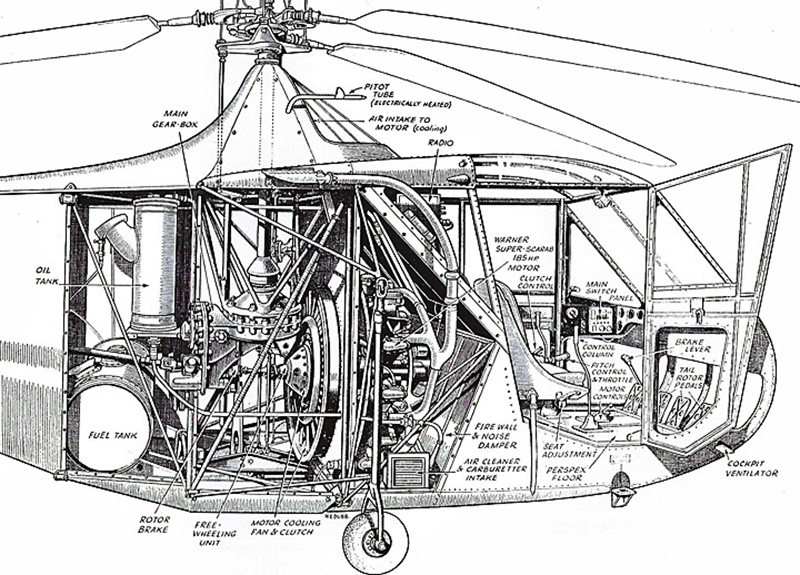
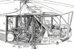
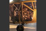
Power was supplied by a 200 hp (Take Off 5 minute rating) Warner Super Scarab R550-3 air-cooled seven cylinder radial engine. This was mounted with the propeller shaft horizontal, but the engine faced “backwards,” with the propeller shaft pointing aft. This drove a short driveshaft connected to the main gearbox. The output shafts from this gearbox provided power to the main rotor, and also to an aft driveshaft that powered the tail rotor.
Cooling Fan and Flywheel
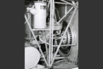
The engine cooling fan and flywheel provided cool air for the engine and contained a manually operated clutch to connect the engine to the main gearbox. The clutch was engaged by a 3 position lever located between the seats in the cockpit that engaged and released both the clutch and rotor brake.. A free-wheeling unit was attached to the output side of the fan which disconnected the engine from the main gear box in the event of engine failure to allow autorotation.
Landing Gear
The landing gear was of the “conventional” tail wheel type, with skids provided on the front to prevent nose-overs during landing. The skids were normally removed as a weight saving on all helicopter not used in pilot training missions. Provisions were provided to move the tail wheel 3 bays aft when the helicopter was used for training. The two-place cockpit was in the nose, immediately ahead of the engine, and arranged so the pilot and trainee sat side-by-side, with entrance doors provided for each. The pilot sat in the right hand seat, opposite of the airplane standard, where the pilot was on the left side. During training the student flew in the right seat and the instructor pilot in the left seat to allow the student to have the cyclic stick in his right hand. Pictures in the Archives files indicate that the R-4 and HNS-1 helicopters were flown from either seat depending on the mission.
Cockpit
The cockpit was extensively glazed with Plexiglas windows, and doors were provided on each side. In addition to the windshield, roll down windows were placed in the doors, windows in the cockpit overhead, and the nose below the instrument panel. Cockpit floors were Haskelite (Birch plies impregnated with phenolic resin and molded under pressure and heat (280 degrees) to form a lightweight structural material).
Fuselage
On the R-4, the fuselage structure was made in two pieces, bolted together just aft of the engine bay. The aft structure was almost entirely round steel tubing, but the forward part also included square-section steel tubing and wooden stringers. The aft framework was covered with doped fabric to reduce drag. Zippers were sewn into the fabric at various locations to allow access to components for inspection and maintenance. The forward structure,containing the engine compartment and cockpit was covered with removable panels made from thin sheets of dural (hardened aluminum alloy) or magnesium alloy. The fuselage framework was constructed almost entirely of 4130 chrome-molybdenum steel thin wall tubing.
Rotor Hubs
Because weight is critical on all aircraft and especially on helicopters, lightweight aluminum and magnesium alloys were applied wherever possible. The main rotor hub was made of steel, but the swashplate control assembly was made of magnesium alloy hubs with aluminum alloy plates riveted on.
Flight Control
The S-47 (R-4B) flight control system consisted of dual azimuth (360 degree) control (Cyclic) sticks, which controlled the direction of flight and a single Main Pitch Control Stick (Collective), which controlled vertical movement was mounted between the 2 cockpit seats. A twist grip on the end of the Main Pitch Control Stick controlled engine rpm and was synchronized to increase rpm when main rotor pitch was increased and decrease rpm when pitch was decreased. Two rudder pedals controlled the pitch of the anti-torque tail rotor which controlled the direction of the fuselage
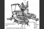
Lateral (Roll) Control. Lateral control was obtained by side movement of the cyclic stick. Side movement of the stick raised or lowered the azimuthal control horn on the azimuthal control spider (stationary star) which in turn tilted the blade incidence control spider (rotating star).
Longitudinal Control. Logitudinal control was obtained by fore and aft movement of the cyclic stick. Fore and aft movement of the stick raised or lowered the second azimuth control horn which tilted the rotating star. A combination of lateral and longitudinal movement of the cyclic stick would allow the helicopter to fly in any direction.
Vertical Control. Vertical (Up and Down) control was obtained by up and down movement of the Main Pitch Control Stick which increased or decreased the pitch of all 3 main rotor blades by means of a push pull rod enclosed in the main rotor shaft. The blade pitch was increased or decreased simultaneously by a sliding section of the crown on the main rotor hub.
Main Gearbox
The main gearbox housing was a cast magnesium alloy in three parts. All gears and shafts were alloy steel. The driveshaft from the engine drove a 17-tooth helix pinion gear which meshed with and drove a helix gear of 52-teeth. The 52 tooth gear was mounted on a common shaft with an 18 tooth spiral bevel pinion gear and the two gears were bolted together. The 18 tooth pinion gear meshed with and drove a 55 tooth spiral bevel ring gear which was attached to the lower end of the main rotor drive shaft. The total reduction in this transmission, between the engine and the main rotor was 1 to 0.107 (2,000 engine rpm = 215 main rotor rpm). The main gearbox also provided power to the tail rotor through the tail drive shaft.
Main Rotor Blades
The main rotor blade had a step tapered, tubular chrome-molybdenum steel spar extending from root to tip. Welded to the spar were stainless steel collars to which spruce plywood ribs were bolted. The leading edge consisted of lamination of spruce, balsa, and mahogany and the trailing edge formed by a flexible cable held to the ribs with brass clips. Balsa wood was used for the fairing at both tip and root of the blade. The blade was covered by fabric doped to the wood surfaces and sewn to the ribs. The leading edge of the outer 1/3 of the blade including the tip was covered by a brass leading edge cover (abrasion strip) attached by countersink brass screw which were soldered over and trimmed to contour. A NACA 0012 airfoil was used.
To correct vibration problems in early production helicopters, which were holding up deliveries, a production helicopter was tied down and load cells installed on the pitch links. The load cells recorded the forces in each of the 3 pushrods which varied by rpm and pitch. Bending the brass clips, which attached the trailing edge cable to the ribs, acted the same as trim tab adjustments on modern main rotor blades to lower vibrations to an acceptable level for Government acceptance. Blades were adjusted in sets of 3. Interchangeability of individual blades would not be available until all-metal blades were produced in the 1950s.
Pitch Gage
The R-4 helicopter was equipped with a pitch gage to indicate the blade angle for the main rotor. The gage was mounted on top of the instrument panel just right of center and consisted of a vertical tube with a longitudinal slot facing aft. Projecting through the slot was a luminous button attached to a spring loaded piston in the tube. The piston was connected directly to the bottom of the pitch control lever (collective) by a pull wire. Readings showed the general pitch setting of the main rotor blades and was scaled from 2 ½ degrees at the bottom to 14 degrees at the top. It was suggested that 10 degrees be used for take-off and 2 ½ degrees for autorotation.
Tail Rotor Blades
The tail rotor blades were all wood. The spar was made of spruce, with alternating laminates of maple and mahogany filling out the airfoil. The whole tail rotor blade was covered with fabric, and a thin brass sheet was molded and fastened to the leading edge to protect against erosion.
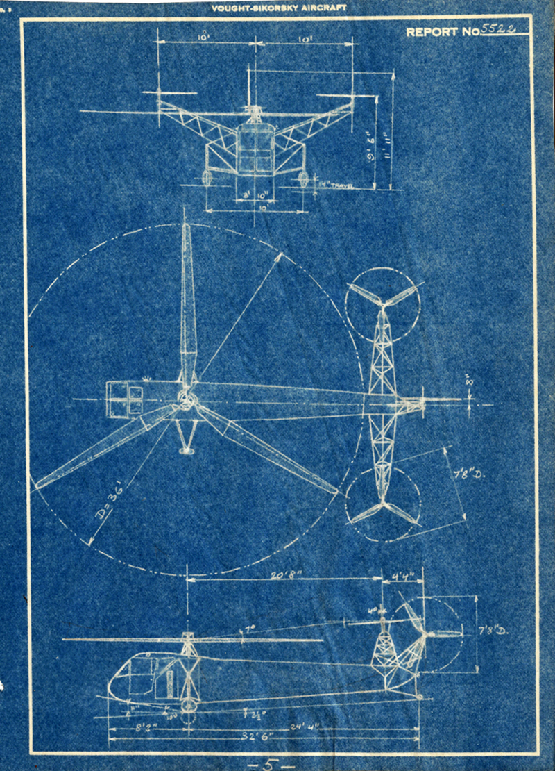
General Arrangement Drawing
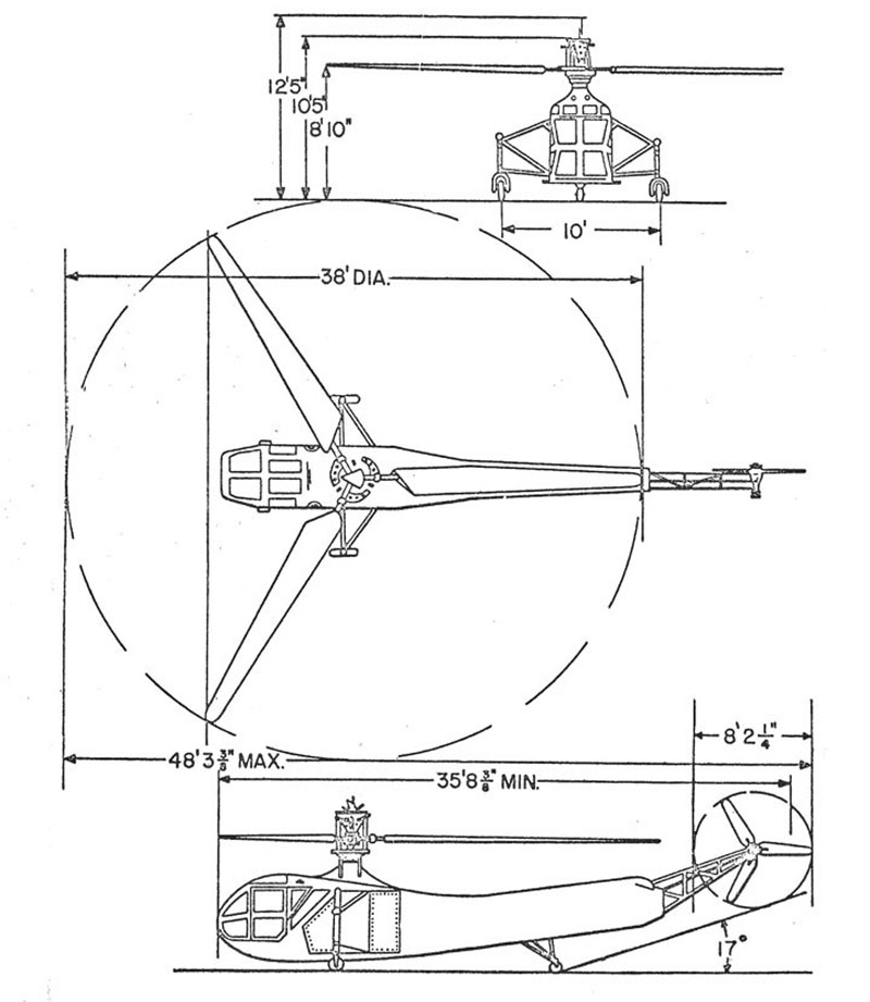
Mission Systems
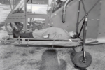
The tactical mission of the S-47 helicopter was for observation, courier missions, and assisting the artillery by locating suitable targets and adjusting fire. A litter installation was available for carrying one person externally.
The YR-4B model has bomb racks installed and was capable of carrying three 100 pound demolition bombs or one 325 pound depth bomb. The Government deleted the bomb rack requirement for R-4B production models.
Rescue Hoist
The U. S. Coast Guard designed a hydraulic rescue hoist capably of hoisting 400 pounds at 2 ½ feet per second for use on the R-4 (HNS-1) helicopter. Sergei Sikorsky describes the development of the rescue hoist in the April 2011 Sikorsky Archives Newsletter.
General Characteristics and Performance S-47(R-4B)
PERFORMANCE
Standard Day, Sea Level
| Maximum speed (Vne) | 82 mph 71.3 kts 132 km/hr |
Cruise speed | 65 mph 56.5 kts 104.6 km/hr |
Range | 153 miles 246.2km |
Service ceiling | 12,000 ft 3,657.6 m |
Rate of Climb | 660 ft/min 201.2 m/s |
WEIGHTS
Maximum takeoff gross weight | 2,540 lbs 11,52.1 kg |
Weight empty | 2,020 lbs 916.3 kg |
Maximum fuel load | 30 gal 113.6 ltr |
GENERAL DATA
Crew seating capacity | 2 |
POWERPLANT RATINGS
Standard Day at Sea Level
| Warner Super Scarab R550-3 (Take Off rating) | 200 hp 149 kw |
AIRCRAFT DIMENSIONS
Main rotor diameter (blade tip circle) | 38’ 0” 11.6 m |
Tail rotor diameter (blade tip circle) | 8’ 2.25” 2.44 m |
Fuselage length | 35’8.375″ 10.7m |
Length over-all (including rotors) | 48’8.375″ 14.6 m |
Height over-all | 12’ 5” 3.66 m |
Main landing gear tread | 10′ 0″ 3.05 m |
Production History
S-47 (R-4) production consisted of 131 helicopters. All R-4 model helicopters were built under USAAF contracts and assigned USAAF Serial Numbers. Some were later transferred to the U.S. Navy/U. S. Coast Guard and identified as HNS-1 helicopters with Navy Bureau Numbers (BuNo) assigned. Others were exported to Britain under the Lend Lease program were assigned Royal Air Force and Royal Navy Serial Numbers and named the Hoverfly.
- 1 XR-4. Converted to the XR-4C configuration in 1943.
- 3 YR-4A
- 27 YR-4B
- 100 R-4B ( Distribution: 40 USAAF, 19 USN/USCG, 41 RAF/RN)
Additional Information:
Anything A Horse Can Do. The Story of the Helicopter
H. F. Gregory (1944) ISBN-10: 1430497505
Sikorsky YR-4B WWII Aircraft Equipment Recovery. A 6 minute silent film shot on May 2, 1945. The helicopter is a YR-4B of the 10th Air Force Air Jungle Rescue Unit. One of their tasks was to fly out to wrecked aircraft and paint a big yellow “X” on it so that it would not be reported as a new crash and then to recover the more useful instruments.
- by Vinny Devine
Related Articles
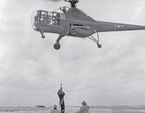
Sikorsky Recognizes Rescues
The life-saving power of the helicopter was clear soon after Sikorsky Aircraft began S-47 production in Bridgeport, Connecticut in 1942.
Sikorsky Lifts the Army
The U.S. Army saw the possibilities of the helicopter early in its development, thus beginning a relationship with Sikorsky Aircraft that continues to this day.
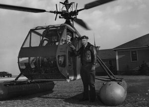
The World’s First Helicopter Mercy Flight
During a severe snowstorm in January 1944, U.S. Coast Guard Lt. Commander Erickson performed the first helicopter mercy flight in his HNS-1, saving several lives.
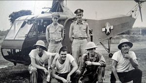
The World’s First Military Combat Rescue
The first military combat rescue by helicopter was performed in April 1944 by U.S. Armed Air Forces Second Lt. Carter Harman.
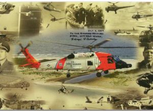
Sikorsky Serves the Coast Guard
A flight demonstration of Igor Sikorsky’s VS-300A helicopter at Bridgeport, Connecticut in April 1942 started an air-sea rescue revolution in the U.S. Coast Guard.
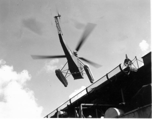
The First Military Use of the R-4
John H. Donovan recollects the first military use of the helicopter, during World War II in Guam.
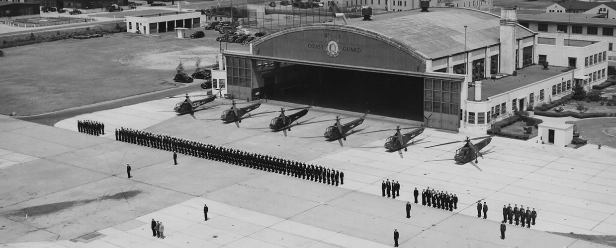
The Eyes and Ears of the Convoy: Development of the Helicopter as an Anti-Submarine Weapon
Starting in World War II, the U.S. Coast Guard was visionary in helping expand the uses of a helicopter.
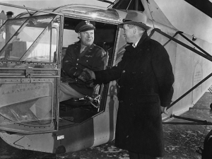
Delivery of the 100th Sikorsky R-4B
Photos from the delivery celebration for the 100th R-4B helicopter in December 1944.
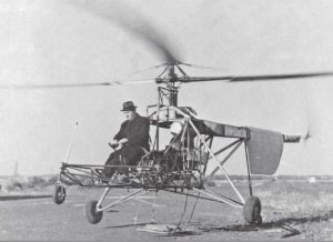
Igor Sikorsky Solves “The Helicopter Problem”
When Igor Sikorsky first flew his VS-300 helicopter on September 14, 1939, he made vertical flight discoveries that shaped helicopters to this day.
Predictions of a Pioneer
Igor Sikorsky’s predictions for air travel in general and for helicopters in particular have been largely realized or surpassed.
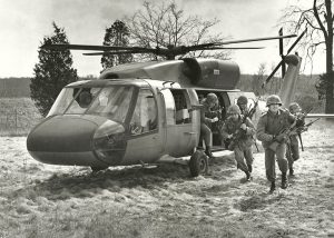
Ray Leoni: Recollections of a Sikorsky Junior Engineer
Ray Leoni recollects his 41-year career at Sikorsky Aircraft, beginning as a junior engineer and retiring as a Senior VP of Engineering and Advanced Programs.
History in the Making: The First Helicopter Delivery
Chief Test Pilot Charles Lester Morris remembers performing the first helicopter delivery, a five day journey to Wright Field in Ohio.
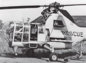
Sikorsky Helicopters in U.S. Air Force Rescue Squadrons
The HH-60W Combat Rescue Helicopter is the latest in the life-saving line of Sikorsky helicopters made for U.S. Air Force Rescue Squadrons. The Whiskey will round out a century of vertical flight rescue heroism.
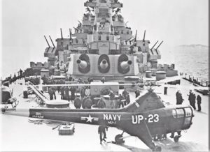
Sikorsky Helicopters Came of Age in the Korean War
Prior to the Korean War, the U.S. armed forces had few helicopters and little combat helicopter doctrine. The Korean conflict drove rapid combat helicopter development.
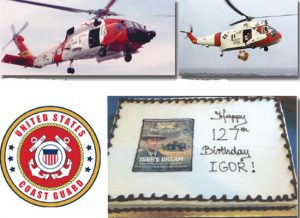
U.S. Coast Guard and Sikorsky Celebrate Significant Events
The United States Coast Guard and Sikorsky Aircraft celebrated two significant events in 2016. One century of United States Coast Guard aviation and the 127th birthday of Igor Sikorsky.
How Sikorsky Helicopters Are Named
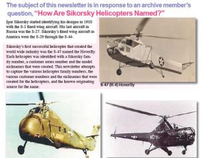
The subject of this newsletter is in response to an archive member’s question, “How Are Sikorsky Helicopters Named?”
75th Anniversary of the S-46 (VS-300)
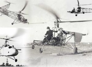
During this period, Sikorsky Aircraft designed, developed, and produced the S-47 (R-4), S-48 (S-5), S-49 (R-6), S-51, S-52, and S-55 helicopters.
70th Anniv. of the First Helicopter Humanitarian Mission
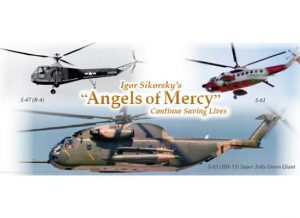
Igor Sikorsky’s “Angels of Mercy” continue to save lives. 2014 marks the 70th anniversary of the first helicopter humanitarian mission in the world.

