Sikorsky Product History
Sikorsky S-57
Background
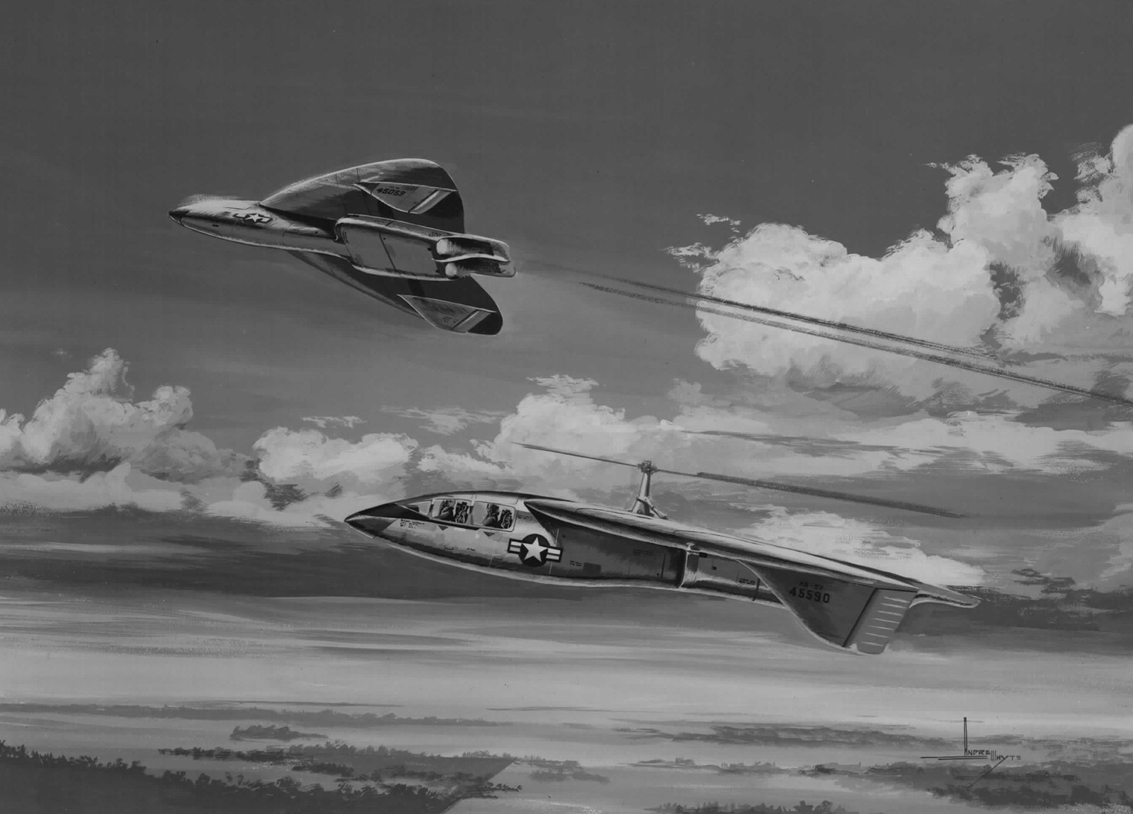
In the late 1940s the basic concept of the helicopter had been proven and numerous aircraft were in production. Design engineers then set their sights on how to extend the helicopter’s speed envelope. Conventional helicopters are speed limited to about 180 knots due to the rotor’s inability to generate lift and forward propulsion at higher speeds. Many companies were experimenting with high speed concepts to overcome these limitations. Sikorsky proposed a “stowed rotor”, where the helicopter rotor was stopped and retracted into the top of the fuselage of a fixed wing aircraft. To make the geometry work, a single bladed rotor was envisioned with a large counterweight to replace the opposite blade.
The Igor I. Sikorsky Historical Archives, Inc. has numerous documents on the history of Mr. Sikorsky’s life and career, and the history of the company he founded. One of the most interesting documents is an unpublished book written by “Prof” Sikorsky, Igor’s cousin, prior to his retirement in 1968. It documented the various aircraft produced by Sikorsky up to that time. Much of the following information on the S-57 Convertiplane and “Stowed Rotor” aircraft is taken directly from that unpublished book:
“Aviation development in fixed-wing aircraft was being applied to increased speed with a resulting increase in take-off and landing runs. The helicopters capable of vertical landings and take-off were limited in their design mission because of insufficient cruising speed and range. Numerous configurations, entitled “Convertiplanes”, were proposed by industry. These configurations combined the vertical take-off features of the helicopters and the forward-flight-and-range characteristics of fixed-wing aircraft.”
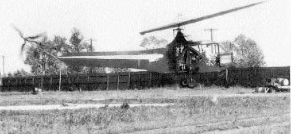
The concept of a stowed rotor V/STOL aircraft was originated by Sikorsky Aircraft in the late 1940s. It was recognized early that stowing the rotor into the fuselage would be difficult due to the rotor size in relation to the airframe. This led to the unusual idea of using a single bladed rotor with a counter weight. This was flight tested on a Sikorsky R-4 helicopter in August 1948. The blade counterbalance proved acceptable, but the aerodynamic vibratory loads were a concern. The test did give the design team sufficient encouragement to proceed with the concept.
“In 1949, an aircraft was envisioned which resembled a helicopter to the extent of having a lifting rotor, but which also incorporated the unique feature of being able to stop the rotor in flight, stow it, and then proceed as a conventional aircraft. At that time, an aircraft was foreseen which could incorporate into a single vehicle both the desirable hover characteristics of a helicopter and the high speed performance of a fixed wing aircraft. The technical knowledge required to achieve this combination was the subject of intensive study from 1951 through 1958. During this interval, the US Air Force actively supported the development of this concept under two contracts with Sikorsky Aircraft.”
“In early 1950, a joint Air Force-Army design competition was held to select various convertiplane configurations for a design study phase. This was to include preliminary engineering, wind tunnel tests and a mockup. These designs were to be used for observation and reconnaissance missions, and to explore the feasibility of application of convertiplane principles to larger aircraft. Three convertible configurations were selected – the unloaded rotor principle proposed by McDonnell Aircraft [the XV-1 compound helicopter with a reaction drive rotor system], the tilting rotor configuration proposed by Bell Aircraft Corp. [the XV-3], and the single bladed fully retractable rotor proposed by Sikorsky Aircraft Division [the XV-2].
“Numerous rotor and propulsion systems were examined [by Sikorsky] in an attempt to achieve the most favorable aircraft configuration. This early work was severely hampered by limited gas turbine technology since both the characteristics and selection of turbines in the early 1950s were unfavorable. Gas-driven rotor systems were examined, but were restricted to relatively low rotor disc loadings in the order of four lbs. per sq. ft. The resulting geometrical difficulties of stowing a large diameter rotor were simplified to a large extent by the use of a single blade rotor system. Accordingly, these early configuration studies were based on a counterweighted single bladed main rotor with cold cycle propulsion.
“The Sikorsky model S-57 stowable-rotor convertiplane design was developed…during 1951, 1952, and 1953. Several configurations were studied during that period, but the final design was essentially a jet-powered airplane with a one-bladed, counterbalanced, pressure-jet rotor which could be stopped and started in flight; thus providing both helicopter and airplane flight characteristics in the same aircraft. To prevent excessive blade flapping at low rotor speeds, the design provided for the flapping hinge to be locked below 25% of the design rotor speed. In this regime, lift forces on the blade are transmitted directly to the aircraft as moments which could produce pitching and rolling motion of the aircraft. During a normal autorotation stop, the blade drag at zero blade lift provides the torque necessary to stop the rotor. A normal start would be made by using power to start the rotor at zero blade lift. Hence, for normal starts and stops, the blades would contribute essentially no rolling and pitching disturbances even though locked.
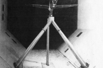
“Simultaneously with the design studies, a twentieth scale wind tunnel model of a dart wing aircraft configuration was tested in 1951 to provide information on stability and control about all axes. Modifications to wing and control surface designs were made as a result of these tests. At that time it was decided that design work should be limited to that required to establish the general size and weight of the aircraft. The most important technical aspect of this concept centered about the rotor system during conversion. In particular, the rotor behavior from an aeroelastic and control standpoint during conversion was identified as the critical aspect of this concept. It was, therefore, agreed by [the Air Force-Army] and Sikorsky Aircraft that all future effort should be focused on this area. To this end, a one-fifth scale gas-driven, single blade rotor was designed in 1952, after determination that a full size rotor … was impractical due to lack of a suitable engine-load compressor combination.
“In 1953, fabrication of this scale rotor was completed. It was then tested on the outdoor rig to verify nozzle, ducting, and aerodynamic performance and to determine basic structural integrity. Following this, the rotor was installed in the Massie Memorial Wind Tunnel at Wright Field. An aerodynamically similar model of the airframe was also constructed which allowed evaluation of the mutual effects of wing and rotor. Both dart and conventional tapered trapezoidal wing planforms were tested in the Massie tunnel for approximately three months. During this investigation, the autorotational characteristics of a flapping and of a locked rigid blade were determined for a rotor advance ratio from 0.3 to infinity. Acceleration and deceleration characteristics were determined as a function of shaft angle of attack, blade collective and blade cyclic control inputs. Information was obtained with regard to aircraft rolling and pitching moments produced during rotor starting and stopping. The sensitivity of these moments to rotor control inputs was also determined. Rotor dynamic behavior in passing through all blade resonant frequencies during acceleration and deceleration was also studied in detail. This first Air Force contract was completed in July 1954. Considerable knowledge was gained regarding the Stowed Rotor concept, particularly with respect to rotor behavior during conversion. Information was obtained as to sensitivity to rotor control and time history of moments produced during the phase when rotor flapping is locked out.”
Although not clearly explained in the Prof Sikorsky book, these test results were not fully successful, and the design team moved on to a two-bladed rotor as described in a latter section of this write-up.
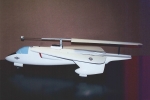
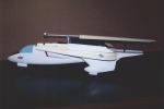
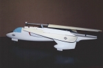
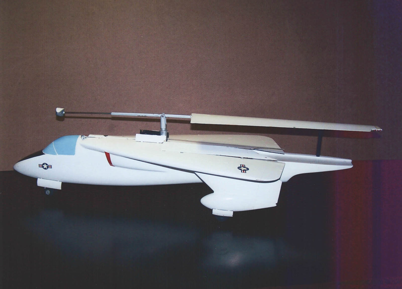
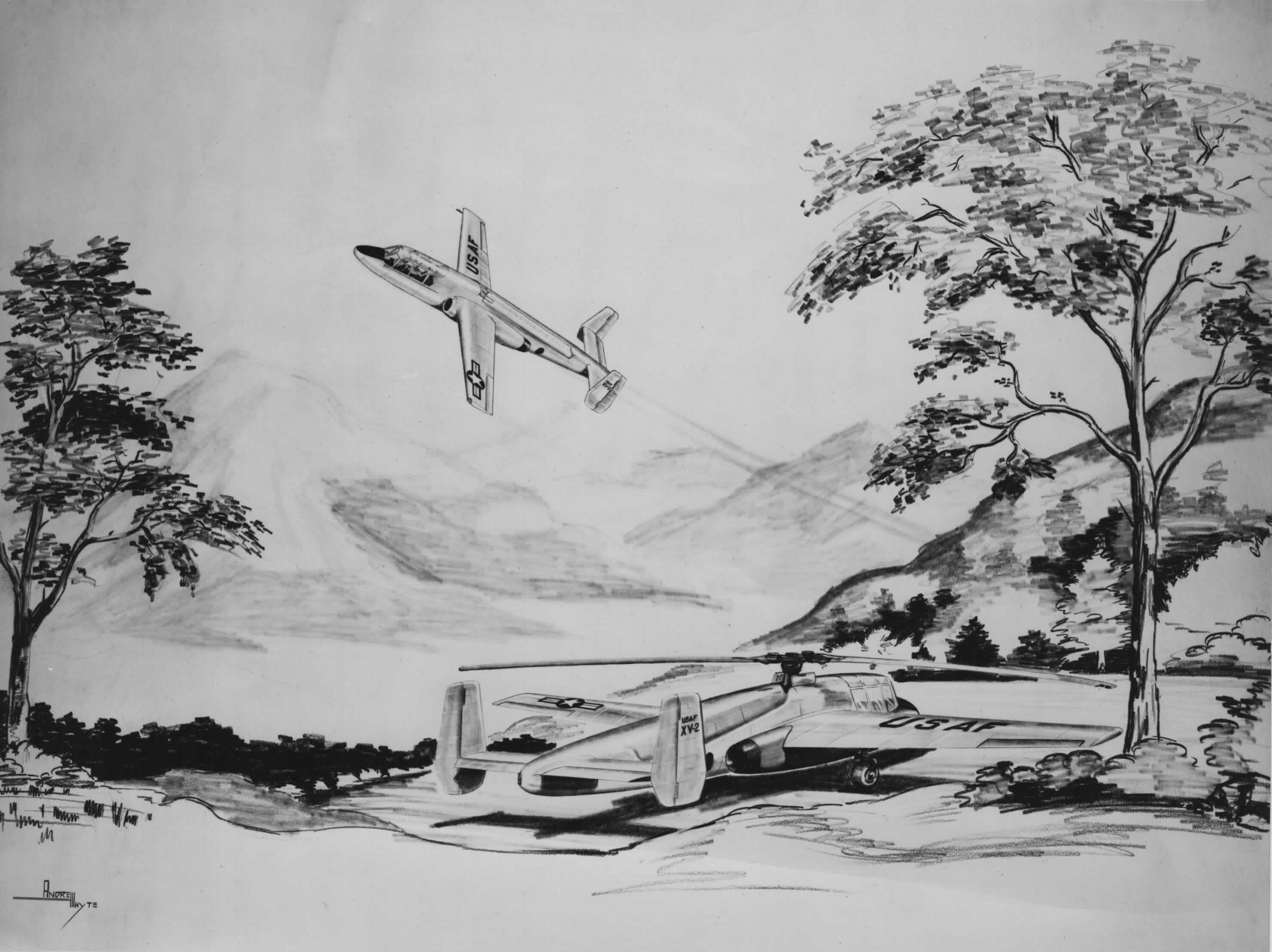
Also note that the aircraft configuration was evolving. The isometric cutaway drawing shown above and the three-view drawing shown below are of the initial configuration with rotor stopped, the blade rotated 90º about its pitch axis, and stowed on top of a large pylon on the top of the aircraft. The painting shown earlier and the display model shown below have a cleaner design where the stopped rotor is retracted into the fuselage.
Configuration Features
The unique configuration of a single counterweighted blade was driven by the low disc loading technology of the time. The S-57 disc loading (gross weight/rotor disc area) was only 2.9 lbs/sq. ft. Many modern helicopters have disc loadings of around 10 lbs/sq. ft. or even higher. This led to a very large rotor in relation to the size of the aircraft itself. And thus the decision to try a single blade so that it could be stopped and stowed as the aircraft was converted to a high speed fixed wing.
Three vertical fins were initially included. On the early configuration the center fin included the rotor pylon extending from the rotor to the tail of the aircraft to provide the structure to support the stopped rotor blade. The outer fins were mounted just inboard of the elevons on the underside of the wing and included rudders for fixed wing yaw control.
The airplane configuration was also a technological stretch. It used a “delta” wing with an aspect ratio of 1.37 to 1, and a taper ratio of 3.6 to one.
 The rotor is stopped and aligned with the aircraft’s longitudinal axis
 Doors open on the top of the fuselage and the counterweight is retracted inward
 The rotor shaft is tilted forward lowering the rotor into the fuselage
 The doors close and the aircraft continues in the fixed-wing configuration
 Model of S-57 with the rotor retracted into the fuselage
The rotor blade construction was envisioned to be an aluminum extruded spar with aluminum trailing edge ribs, skin and tip. The compressed air for the tip drive passed through the spar.
The engine was to be installed in the rear portion of the fuselage. A compressor, driven by the engine, was installed forward of the engine to provide the compressed air to drive the rotor or a tail nozzle for fixed wing propulsion.
Conventional helicopter flight controls were to be used. The cyclic stick was to control both the rotor and the elevons on the trailing edge of the wing. The rudder pedals would also control the rudders. Quoting a Sikorsky report at the time: “Directional control in the helicopter hovering condition will be accomplished through the use of a new and novel directional control device operated off the main rotor, since no anti-torque rotor will be used.” No further details were provided.
A two person cockpit was included for a pilot and a copilot/observer.
The rotor stopping and stowing concept for the second configuration is illustrated by the following photographs of a 1/16.7th scale demonstration model.
General Arrangement Drawing – Initial Configuration
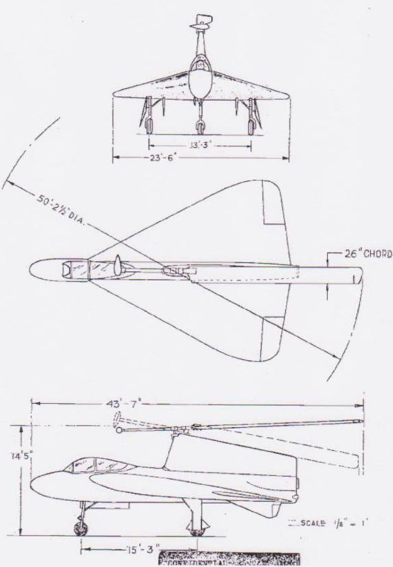
General Characteristics and Performance
Performance Standard Day at Sea Level | |
|---|---|
Cruise Speed | 120 kts |
High Speed | 165 kts
|
Potential Maximum Speed (Vne) | 300 – 400 kts |
Hover Endurance | 30 mins
|
Cruise Endurance @ 30 mins Hover Endurance | 1.5 hrs |
Altitude Lost During Auto-rotative Rotor Start | 300 ft |
Weights | |
|---|---|
Design Gross Weight | 5,800 lbs |
Maximum Payload | 600 lbs |
Powerplant Ratings Standard Day at Sea Level | |
|---|---|
Wright GT-43 Typhoon Turboprop | 1320 hp (max power) 1050 hp (normal power) |
Aircraft Dimensions | |
|---|---|
Rotor Diameter (Blade Tip Circle) | 50′ 2.5″
|
Number of Blades | 1 |
Blade Chord | 26 in |
Wing Span | 23′ 6″ |
Related Models
Continuing the direct quotes from the Prof Sikorsky unpublished book:
“The second contract…was awarded in May 1955, to evaluate the aerodynamic characteristics of a two-bladed rotor and to verify the semi-empirical theories developed during the previous contract. A two-bladed rotor was designed and fabricated having a diameter of 10 ft. and incorporating a stowing feature to permit the blades to fold back along the aircraft’s longitudinal axis. Blade folding was required as a result of the low disc loadings and the consequent large diameter rotors characteristic of the early aircraft designs.
“This two-bladed rotor was installed in the United Aircraft 18 ft. wind tunnel in 1957 and subjected to extensive testing to determine rotor behavior during all phases of the starting, stopping and steady operation.
“During the period of tunnel testing, theoretical studies continued to evaluate aircraft behavior during the transition. An iterative calculation procedure for analysis of the rotor during transition was completed. In addition, analytical studies were made of the time history of pitching and rolling moments experienced during autorotative starts and stops, including the determination of the altitude lost during an autorotational start.
“Work on the second contract was discontinued by the Air Force in April, 1958 at which time it was approximately eighty percent complete. Termination was motivated by concurrent financial commitments to the developing space and missile programs.”
“In 1951 to 1958, during the terms of the two Air Force contracts, considerable knowledge was gained to provide the groundwork for the present [mid-1960s] Stowed Rotor investigations. Specifically, techniques were empirically developed to control rotor behavior during the conversion phase. In addition, the foundation was laid for development of the theoretical methods required to permit calculation of blade aerodynamic and structural characteristics.
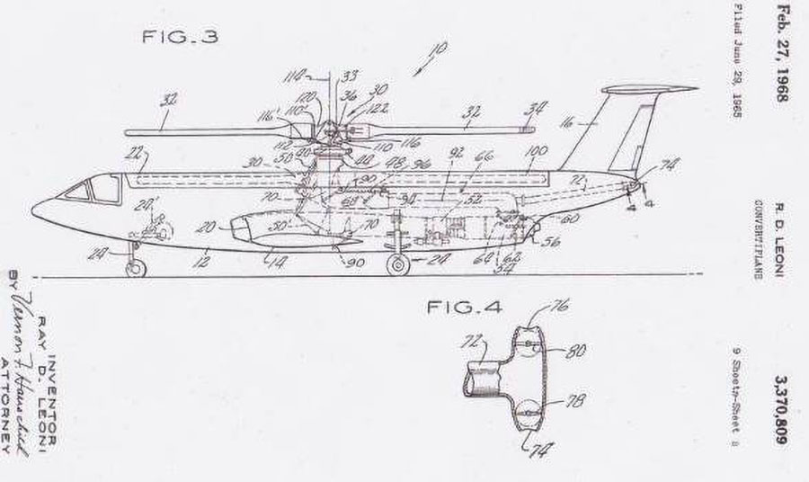
“…1n 1963, design work on the Stowed Rotor concept was actively resumed at Sikorsky Aircraft. Advances in technology combined with new concept requirements have permitted design approaches to be pursued which in the earlier period were considered impossible. Vastly improved gas generators, in particular, have had a profound effect on the latitude of design parameters which can be considered for the Stowed Rotor concept. Specifically, the new light weight turbines allow higher disc loading to be used which results in smaller rotor diameters relative to aircraft size. This reduction in diameter, as compared with earlier design studies, has a significant effect on rotor stowing in terms of simplifying both rotor hub structure and stowing mechanism. For instance, it is now feasible to completely stow a two-bladed rotor without having to fold the blades prior to stowing.
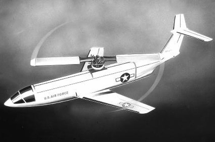
“In addition, smaller rotor diameters result in a reduction in rotor induced pitching and rolling moments during periods of rotor acceleration and deceleration. This is a positive contribution to lessening aircraft susceptibility to gust disturbances during the conversion mode. A further recent technological benefit to the Stowed Rotor concept is the availability of metallurgical information at elevated temperatures. This has expanded the options of propulsion systems beyond the cold cycle drive system originally chosen in the early 1950s. The concept in its present configuration uses the hot cycle system in which the turbine exhaust is ducted through the blade and expanded through tip nozzles. Also, the new high pressure ratio gas generators for this type of system. As compared with earlier aircraft designs employing the stowed rotor concept, the new design approach completely eliminates the need for load compressors, shafting, power turbines, and gear boxes. Simplicity of design and versatility of operation are outstanding attributes of this concept”
“In the mid-sixties the Air Force Aerospace Rescue and Recovery Service had a requirement for a long range hovering aircraft for rescue of downed flight crews in Vietnam. This was the CARA (Combat Aircrew Recovery Aircraft) program. Sikorsky teamed with North American Aviation and proposed a Stowed Rotor concept for this mission. Sikorsky was responsible for the propulsion and vertical lift systems, while North American handled the high-speed conventional jet aircraft design.” The CARA used a four bladed rotor with two blades folded forward and two aft prior to retracting them into the fuselage.
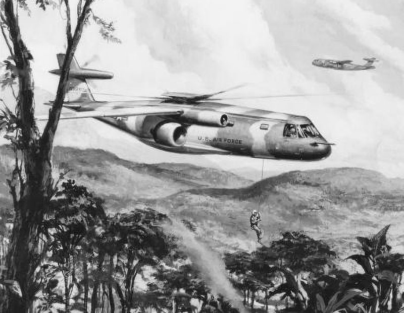
The combination of the development time and cost for any of the proposed aircraft, plus the desire for a near-term solution, resulted in the Air Force not proceeding with the program.
At this point the stowed rotor had numerous technical issues yet to be resolved and few production possibilities. Therefore, the stowed rotor designs and studies were terminated. High speed helicopter efforts at Sikorsky were next directed to a compound helicopter (the S-61F) with a wing and auxiliary propulsion to offload the rotor and achieve higher speeds. Although not having the speed potential of the stowed rotor, it had the potential to increase helicopter speeds with much less complexity and technical challenge.
Additional Information Resources
U.S. patent 3,370,809, Convertiplane, R.D. Leoni, submitted on June 29, 1965. 25 claims. Granted on February 27, 1968
- by Art Linden
Related Articles
Sikorsky Aircraft Paintings by Andy Whyte
This issue of the newsletter is devoted to the aircraft designs and paintings by Andy Whyte, who had a 40 year career at Sikorsky Aircraft.

