Sikorsky Product History
Sikorsky S-46 / VS-300 / VS-300A
Background
When Igor Sikorsky developed his first helicopters, the H-1 and H-2 during 1909 and 1910, he found that the aircraft materials, engines and other technologies available at the time were not far enough advanced for helicopter flight to be possible. Throughout the next two decades of his career however, Igor continuously monitored these technologies and in as early as 1928, he determined that a viable helicopter was finally within reach. In particular, better engines were available as well as lighter and stronger aircraft materials. In 1931, he applied for a patent for a single main rotor helicopter that included nearly every feature that would be incorporated in the VS-300 helicopter.
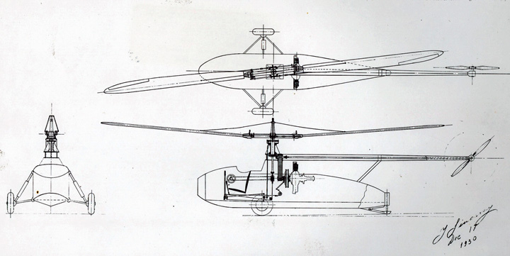
By 1938, technology had finally caught up with his dream. When he was summoned to United Aircraft Headquarters in East Hartford, Connecticut to be told that the Sikorsky Aircraft company was being shut down due to a lack of business, he requested that he be allowed to keep his design team together to design a helicopter. His request was granted along with an initial budget of $30,000. The VS-300 was America’s first practical helicopter. It was also the first successful helicopter in the world with a single main rotor and a torque compensating tail rotor.
During the 1930s when the Sikorsky Aircraft company was busy producing fixed wing flying boats, Igor Sikorsky and his engineering team were also spending a significant amount of time outside of their working hours completing preliminary engineering designs of helicopter concepts. So, in late March 1939 when United Aircraft management approved work to begin on a helicopter demonstrator, the team wasted no time on getting to work. Igor Sikorsky committed to having a helicopter prototype completed in five months, by the end of August 1939.
VS-300 Development Timeline
Igor Sikorsky Submits Helicopter Patent Application
Helicopter Proposal Approved
Work Begins on the VS-300
First Flight
First Configuration Damaged
2nd Configuration First Flight
First flight Out of Yard
First Public Demonstration
Franklin Engine Installed
Endurance Record Set
First Water Landing
International Endurance Record Set
3rd Configuration First Flight
Final VS-300A Configuration First Flight
Hydraulic Dampers Installed
Final Flight
Configuration Features
Igor Sikorsky and his development team considered the VS-300 to be a flying test bed to experiment with helicopter technologies, including rotor systems, flight controls and lightweight materials. Throughout its development, the VS-300 was improved continuously and had four major configurations, as described in more detail in The Design Evolution of the VS-300 Helicopter.
Flight Controls
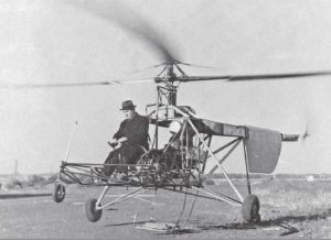
The picture below shows the VS-300 on the day of the first flight. Visible in this picture is the single tail rotor pedal and the collective control wheel, similar to the trim controls on the flying boats, on the right side of the helicopter. The cables from the top of the main rotor to the blades prevented the blades from drooping too much when the blades were not turning.

Collective control for a helicopter controls its vertical movement by changing the pitch angle of the main rotor blades. In the VS-300, the engine throttle was mechanically connected to the collective control so that the engine’s speed adjusted accordingly as the collective pitch was increased or decreased. Igor Sikorsky and the VS-300 team’s solution for collective control was successful and remained essentially the same for all four VS-300 configurations.
Cyclic control for a helicopter, which controls the aircrafts forward, backward and side-to-side movement, was an unsolved engineering problem in 1939. Juan de la Cierva, an early Spanish pioneer of vertical flight who in 1923 developed a successful autogyro design, had attempted to use full azimuthal cyclic control on his autogyro but abandoned it after an unexplained accident. Igor Sikorsky also tried to use it in the first VS-300 configuration, however the team’s design resulted in only very limited control and was determined to be the cause of the accident in December 1939 that destroyed the first VS-300 configuration, the Sikorsky design team abandoned cyclic control in their next VS-300 design, which is known as the second VS-300 configuration. Partial cyclic control was returned to the VS-300 during the Summer of 1941, when lateral side-to-side control was returned to the main rotor in the third VS-300 configuration. Full azimuthal cyclic control, which allowed the VS-300’s main rotor to control aircraft movement in all directions, was finally introduced in the fourth and final VS-300 configuration, after the team finally solved all cyclic control issues.
Flights of the fourth VS-300 configuration, designated VS-300A, began on December 8, 1941 and pilot Charles Lester Morris immediately encountered a strong shaking back and forth of the entire aircraft. This issue was resolved on December 31, 1941 when Igor directed the crew to reinstall dampers, previously used to control blade flapping, in a horizontal position to dampen lead and lag blade movement. This was the “Silver Bullet” and resulted in a smooth flying machine. As a historical note, the XR-4 helicopter with full azimuthal flight controls made its First Flight on January 14, 1942, two weeks after control problems were solved on the VS-300A.
Engine
Power was supplied by a 75 hp (at 3200 rpm) Lycoming O-145-C3 air-cooled four cylinder horizontally opposed engine. The engine was installed with the propeller shaft pointed aft and connected to the main gear box by a series of six V-belts. Tension on the belts was provided by engaging an idler pulley. In July, 1940 the engine was replaced with a 90 hp (at 2,500 rpm) Franklin 4AC-199-E air cooled four cylinder horizontally opposed engine to provide additional power. In April, 1941 an upgraded 4AC-199 engine with 90 hp at 2680 rpm and 100 hp at 3050 rpm was installed.

Cooling Fan
The engine was cooled by a “squirrel cage“, V-belt driven, cooling fan in a sheet metal enclosure mounted above the engine which forced cooling air down across the cylinder cooling fins.
Starter and Battery
In order to save weight the battery was removed from the VS-300 after the first flight. Then the starter was also removed. A handle was installed on the starter and it was held in place to start the engine and then removed. Later the engine was started by a rotary shaft attached to the lower pulley on the engine. After engine start, the rotor was spun-up by hand and then the idler pulley was engaged to tension the 6 drive belts. A bungee cord maintained tension on the idler pulley.


Landing Gear
The original landing gear consisted of 2 main landing gear with diagonal struts and swiveling front and rear wheels. This was soon replaced by vertical oleo struts with swiveling wheels on the main landing gear and a nose wheel. As development progressed diagonal main landing gear was reinstalled and eventually the nose and tail wheel were removed with only a tail skid remaining on the final version.
Fuselage
The original forward fuselage structure framework was constructed almost entirely of 4130 chrome-molybdenum steel thin wall tubing with the aft fuselage an aluminum box structure. In the second configuration the aft structure.was changed to steel thin wall tubing for strength and easy modification.
Drivetrain
A Dural Pulley was attached to the propeller shaft on the Franklin 90 hp engine which was connected to a larger Dural Pulley by 6 V-belts (Gates Vulcco Ropes) for the first rpm reduction of 1.76:1. Shafting from the upper pulley went forward to the main gearbox which contained spiral bevel gears from the rear end (differential) of a Mack truck. This was the second rpm reduction of 5.9:1 to obtain the correct main rotor rpm. A rear shaft ran aft and powered the anti-torque tail rotor and the horizontal rotors on earlier versions by V-belt drive. The upper pulley also contained a free-wheeling unit to allow autorotation in the event of engine failure (No autorotations were attempted with the VS-300).

The Gates Vulco Ropes identified in the illustration were a Gates proprietary design V-belt with concave sides. When the belt was under tension the torque flattened the belt for full contact with the pulley.
Main Rotor Blades
The main rotor blade had a spruce wooden spar extending from root to tip. The leading edge consisted of lamination of spruce, balsa, and mahogany. A high speed (since rotor tip speeds are over 254 mph (374 ft./sec) symmetrical NACA 0012 airfoil was used. This airfoil had a stable center of pressure and the feathering axis and chordwise center of gravity were collocated making it ideal for a rotating wing.


Tail Rotor Blades
The tail rotor blades were all wood. The spar was made of maple, with poplar ribs and birch veneer pockets

VS-300 Flight Simulator
In 1938 Michael Buivid and Bob Labensky designed and fabricated the first helicopter simulator. The configuration of the simulator changed daily and proved to be a valuable tool in predicting pilot’s ergonomic requirements and reactions to tilting fore and aft and laterally, and rotation for directional control.

Rotor Blade Test Unit
The rotor blade test rig was built to measure the lift and torque required to drive various blade designs.

Cargo Carriers

The VS-300 utilized a wicker basket to carry various items to demonstrate the controllability of the helicopter.
On the VS-300A a converted metal bicycle basket replaced the wicker basket.

Amphibious Floats
The VS-300 was originally equipped with 2 Hot Dog floats, a tail float, and a basketball for a nose bumper.

Further along in the program the VS-300A was equipped with longer Hot Dog floats which eliminated the need for the tail float and nose bumper.

General Arrangement Drawing

VS-300A (Fourth Configuration) Performance and General Characteristics
| Performance Characteristics (Standard Day, Sea Level) | |
|---|---|
| Maximum Speed (Vne) | 60 mph / 52.1 kts / 96.6 km/hr |
| Cruise Speed | 35 mph / 30.4 kts / 56.3 km/hr |
| Range | 53 miles / 85.3 km |
| Service Ceiling | 100 ft / 30.48 m |
| Weight | |
|---|---|
| Maximum Takeoff Gross Weight | 1,325 lbs / 601 kg |
| Weight Empty | 1,041 lbs / 472.19 kg |
| Maximum Fuel Load | 14.7 gal / 55.65 ltr |
| Powerplant Ratings | |
|---|---|
| Franklin Model 4AC-199-E (O-200-1) | 100 hp / 73.55 kw |
| Aircraft Dimensions | |
|---|---|
| Main Rotor Diameter (Blade Tip Circle) | 30′ 2″ / 9.14 m |
| Tail Rotor Diameter (Blade Tip Circle) | 7′ 0″ / 2.13 m |
| Fuselage Length | 27′ 11″ / 8.23 m |
| Length Overall (Including Rotors) | 33’ 5” / 10.06 m |
| Height Overall | 8’ 10” / 2.44 m |
| Main Landing Gear Tread | 12′ 5″ / 3.66 m |
- by Vinny Devine
Related Articles
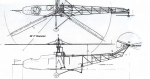
The Design Evolution of the VS-300 Helicopter
The VS-300 helicopter was designed as a research vehicle that was modified iteratively based on flight test results. By the end of its development, only a few parts, including the pilot’s seat, remained from the original helicopter’s design.
Interview with Sergei Sikorsky
Sergei Sikorsky recollects his early life growing up in the Sikorsky household during the era of Sikorsky flying boats and helicopter innovation.
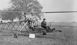
VS-300: The First Practical Helicopter
Igor Sikorsky’s presentation to the Institute of Aeronautical Sciences in 1941 about the development of the VS-300 helicopter.
Igor Sikorsky Solves “The Helicopter Problem”
When Igor Sikorsky first flew his VS-300 helicopter on September 14, 1939, he made vertical flight discoveries that shaped helicopters to this day.
75th Anniversary of the S-46 (VS-300)
During this period, Sikorsky Aircraft designed, developed, and produced the S-47 (R-4), S-48 (S-5), S-49 (R-6), S-51, S-52, and S-55 helicopters.
